
When it comes to connecting pipes in various business programs, SORF (Slip-On Raised Face) flanges play a crucial role. Understanding their dimensions is essential for ensuring a right match and seamless operation. In this guide, we’re going to delve into the information of SORF flange dimensions in easy terms, introduced to you via Renine Metalloys LLP.
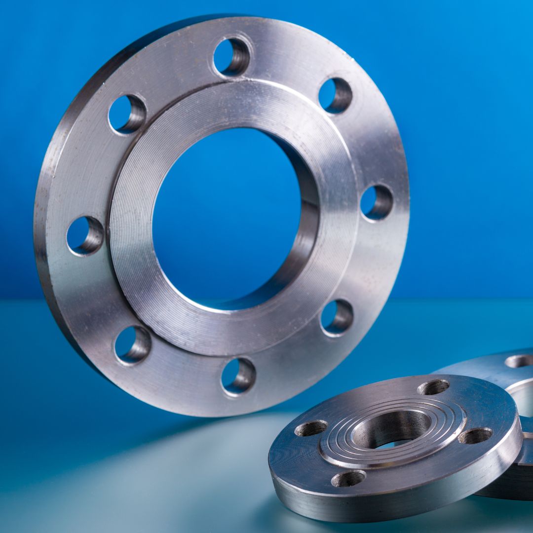
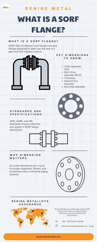
SORF flanges are a sort of pipe flange designed to slide over the quit of a pipe and then welded in region. They characteristic a raised face across the bore hole, which helps create a seal while bolted to a mating flange. Renine Metalloys, a trusted call inside the metallic enterprise, offers a extensive range of splendid SORF flanges suitable for various industrial packages.


Accurate dimensions are essential for making sure right alignment and fitment of SORF flanges. Incorrect dimensions can result in leaks, malfunctions, or even safety hazards in business systems. Therefore, it’s critical to stick to mounted requirements and specs while designing, production, and putting in SORF flanges. Renine Metalloys’ commitment to precision engineering ensures that its SORF flanges meet the very best first-class standards, offering clients with dependable and sturdy solutions for his or her piping desires.
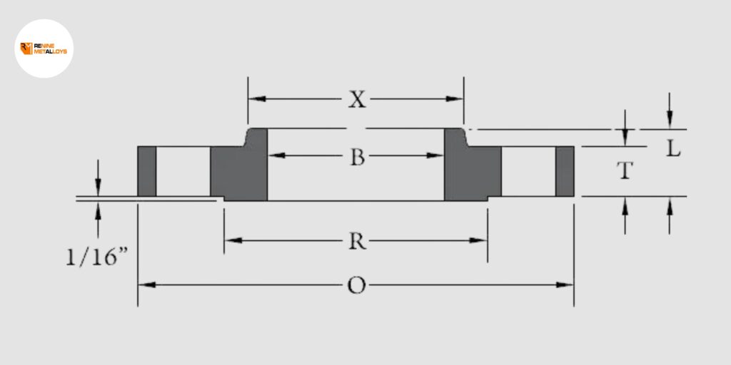
When we talk about SORF flange dimensions in millimetres, we are referring to the measurements of the flange’s various components. These dimensions commonly encompass:
Similarly, SORF flange dimensions in inches follow the identical concepts as millimeter measurements however are expressed in inches. This consists of the outer diameter, bolt circle diameter, thickness, raised face diameter, and bolt hollow diameter.
ANSI requirements specify the scale, materials, and testing requirements for SORF flanges used in numerous industries within the United States. Renine Metalloys ensures that its SORF flanges meet or exceed ANSI requirements for satisfactory and overall performance.
ASME standards, particularly ASME B16.Five, provide unique tips for the dimensions and tolerances of SORF flanges. Renine Metalloys adheres to ASME requirements to make certain the reliability and consistency of its products.
DIN standards are widely used in Europe and specify the scale and materials for SORF flanges used in European industries. Renine Metalloys’ SORF flanges comply with DIN requirements to meet the stringent necessities of European markets.
Dimensions for Slip-on Flanges – From Class 150 to Class 1500, slip-on flange dimensions comply with ASME B16.5. This covers Pipe Flanges and their fittings for sizes NPS ½” up to 24”. For those above NPS 26” up to 60”, ASME B16.47 should be followed.
While examining the dimensions of a slip-on flange, it’s important to inspect several features. These include the Outer and Inner Diameters of the body, the Bolt Circle & Bolt Hole Diameters, and the Length of the Hub. It’s also crucial to ensure the bolt hole’s straightness and alignment.
| Size in Inch | Size in mm | Outer Dia. | Flange Thick. | Hub OD | Flange Length | RF Dia. | RF Height | PCD | Socket Bore | No of Bolts | Bolt Size UNC | Machine Bolt Length | RF Stud Length | Hole Size | ISO Stud Size |
Weight in kg
|
| A | B | C | D | E | F | G | H | |||||||||
| 1/2 | 15 | 90 | 9.6 | 30 | 14 | 34.9 | 2 | 60.3 | 22.2 | 4 | 1/2 | 50 | 55 | 5/8 | M14 | 0.8 |
| 3/4 | 20 | 100 | 11.2 | 38 | 14 | 42.9 | 2 | 69.9 | 27.7 | 4 | 1/2 | 50 | 65 | 5/8 | M14 | 0.9 |
| 1 | 25 | 110 | 12.7 | 49 | 16 | 50.8 | 2 | 79.4 | 34.5 | 4 | 1/2 | 55 | 65 | 5/8 | M14 | 0.9 |
| 1 1/4 | 32 | 115 | 14.3 | 59 | 19 | 63.5 | 2 | 88.9 | 43.2 | 4 | 1/2 | 55 | 70 | 5/8 | M14 | 1.4 |
| 1 1/2 | 40 | 125 | 15.9 | 65 | 21 | 73 | 2 | 98.4 | 49.5 | 4 | 1/2 | 65 | 70 | 5/8 | M14 | 1.4 |
| 2 | 50 | 150 | 17.5 | 78 | 24 | 92.1 | 2 | 120.7 | 61.9 | 4 | 5/8 | 70 | 85 | 3/4 | M16 | 2.3 |
| 2 1/2 | 65 | 180 | 20.7 | 90 | 27 | 104.8 | 2 | 139.7 | 74.6 | 4 | 5/8 | 75 | 90 | 3/4 | M16 | 3.2 |
| 3 | 80 | 190 | 22.3 | 108 | 29 | 127 | 2 | 152.4 | 90.7 | 4 | 5/8 | 75 | 90 | 3/4 | M16 | 3.7 |
| 3 1/2 | 90 | 215 | 22.3 | 122 | 30 | 139.7 | 2 | 177.8 | 103.4 | 8 | 5/8 | 75 | 90 | 3/4 | M16 | 5 |
| 4 | 100 | 230 | 22.3 | 135 | 32 | 157.2 | 2 | 190.5 | 116.1 | 8 | 5/8 | 75 | 90 | 3/4 | M16 | 5.9 |
| 5 | 125 | 255 | 22.3 | 164 | 35 | 185.7 | 2 | 215.9 | 143.8 | 8 | 3/4 | 85 | 95 | 7/8 | M20 | 6.8 |
| 6 | 150 | 280 | 23.9 | 192 | 38 | 215.9 | 2 | 241.3 | 170.7 | 8 | 3/4 | 85 | 100 | 7/8 | M20 | 8.6 |
| 8 | 200 | 345 | 27 | 246 | 43 | 269.9 | 2 | 298.5 | 221.5 | 8 | 3/4 | 90 | 110 | 7/8 | M20 | 13.7 |
| 10 | 250 | 405 | 28.6 | 305 | 48 | 323.8 | 2 | 362 | 276.2 | 12 | 7/8 | 100 | 115 | 1 | M24 | 19.5 |
| 12 | 300 | 485 | 30.2 | 365 | 54 | 381 | 2 | 431.8 | 327 | 12 | 7/8 | 100 | 120 | 1 | M24 | 29 |
| 14 | 350 | 535 | 33.4 | 400 | 56 | 412.8 | 2 | 476.3 | 359.2 | 12 | 1 | 115 | 135 | 1 1/8 | M27 | 41 |
| 16 | 400 | 595 | 35 | 457 | 62 | 469.9 | 2 | 539.8 | 410.5 | 16 | 1 | 115 | 135 | 1 1/8 | M27 | 54 |
| 18 | 450 | 635 | 38.1 | 505 | 67 | 533.4 | 2 | 577.9 | 461.8 | 16 | 1 1/8 | 125 | 145 | 1 1/4 | M30 | 59 |
| 20 | 500 | 700 | 41.3 | 559 | 71 | 584.2 | 2 | 635 | 513.1 | 20 | 1 1/8 | 140 | 160 | 1 1/4 | M30 | 75 |
| 24 | 600 | 815 | 46.1 | 663 | 81 | 692.2 | 2 | 749.3 | 616 | 20 | 1 1/4 | 150 | 170 | 1 3/8 | M33 | 100 |
| Nominal Bore | Dia. (D) | Thick. (E) | Dia. (F) | Dia. (B) | Dia. (A) | Height1 (H) | Nbr | Holes | Dia. (C) |
| 1/2″ | 21.3 | 12.7 | 35.05 | 38 | 22.2 | 21 | 4 | 15.87 | 66.7 |
| 3/4″ | 26.7 | 14.3 | 42.93 | 48 | 27.7 | 24 | 4 | 19.05 | 82.6 |
| 1″ | 33.4 | 15.9 | 50.80 | 54 | 34.5 | 25 | 4 | 19.05 | 88.9 |
| 1 1/4″ | 42.2 | 17.5 | 63.50 | 64 | 43.2 | 25 | 4 | 19.05 | 98.4 |
| 1 1/2″ | 48.3 | 19.1 | 73.15 | 70 | 49.5 | 29 | 4 | 22.22 | 114.3 |
| 2″ | 60.3 | 20.7 | 91.95 | 84 | 61.9 | 32 | 8 | 19.05 | 127.0 |
| 2 1/2″ | 73.0 | 23.9 | 104.65 | 100 | 74.6 | 37 | 8 | 22.22 | 149.2 |
| 3″ | 88.9 | 27.0 | 127.00 | 117 | 90.7 | 41 | 8 | 22.22 | 168.3 |
| 3 1/2″ | 101.6 | 28.6 | 139.70 | 133 | 103.4 | 43 | 8 | 22.22 | 184.2 |
| 4″ | 114.3 | 30.2 | 157.22 | 146 | 116.1 | 46 | 8 | 22.22 | 200.0 |
| 5″ | 141.3 | 33.4 | 185.67 | 178 | 143.8 | 49 | 8 | 22.22 | 235.0 |
| 6″ | 168.3 | 35.0 | 215.90 | 206 | 170.7 | 51 | 12 | 22.22 | 269.9 |
| 8″ | 219.1 | 39.7 | 269.75 | 260 | 221.5 | 60 | 12 | 25.40 | 330.2 |
| 10″ | 273.0 | 46.1 | 323.85 | 321 | 276.2 | 65 | 16 | 28.57 | 387.4 |
| 12″ | 323.8 | 49.3 | 381.00 | 375 | 327.0 | 71 | 16 | 31.75 | 450.8 |
| 14″ | 355.6 | 52.4 | 412.75 | 425 | 359.2 | 75 | 20 | 31.75 | 514.4 |
| 16″ | 406.4 | 55.6 | 469.90 | 483 | 410.5 | 81 | 20 | 34.92 | 571.5 |
| 18″ | 457.0 | 58.8 | 533.40 | 533 | 461.8 | 87 | 24 | 34.92 | 628.6 |
| 20″ | 508.0 | 62.0 | 584.2td> | 587 | 513.1 | 94 | 24 | 34.92 | 685.8 |
| 24″ | 610.0 | 68.3 | 692.15 | 702 | 616.0 | 105 | 24 | 41.27 | 812.8 |
| Nominal Bore | Dia. (D) |
Thick. (E) |
Dia. (F) |
Dia. (B) |
Dia. (A) |
Height1 (H) |
Nbr | Holes | Dia. (C) |
| 1/2″ | 21.3 | 14.3 | 35.05 | 38 | 22.2 | 22 | 4 | 15.87 | 66.7 |
| 3/4″ | 26.7 | 15.9 | 42.93 | 48 | 27.7 | 25 | 4 | 19.05 | 82.6 |
| 1″ | 33.4 | 17.5 | 50.80 | 54 | 34.5 | 27 | 4 | 19.05 | 88.9 |
| 1 1/4″ | 42.2 | 20.7 | 63.50 | 64 | 43.2 | 29 | 4 | 19.05 | 98.4 |
| 1 1/2″ | 48.3 | 22.3 | 73.15 | 70 | 49.5 | 32 | 4 | 22.22 | 114.3 |
| 2″ | 60.3 | 25.4 | 91.95 | 84 | 61.9 | 37 | 8 | 19.05 | 127.0 |
| 2 1/2″ | 73.0 | 28.6 | 104.65 | 100 | 74.6 | 41 | 8 | 22.22 | 149.2 |
| 3″ | 88.9 | 31.8 | 127.00 | 117 | 90.7 | 46 | 8 | 22.22 | 168.3 |
| 3 1/2″ | 101.6 | 35.0 | 139.70 | 133 | 103.4 | 49 | 8 | 25.40 | 184.2 |
| 4″ | 114.3 | 38.1 | 157.22 | 152 | 116.1 | 54 | 8 | 25.40 | 215.9 |
| 5″ | 141.3 | 44.5 | 185.67 | 189 | 143.8 | 60 | 8 | 28.57 | 266.7 |
| 6″ | 168.3 | 47.7 | 215.90 | 222 | 170.7 | 67 | 12 | 28.57 | 292.1 |
| 8″ | 219.1 | 55.6 | 269.75 | 273 | 221.5 | 76 | 12 | 31.75 | 349.2 |
| 10″ | 273.0 | 63.5 | 325.85 | 343 | 276.2 | 86 | 16 | 34.92 | 431.8 |
| 12″ | 323.8 | 66.7 | 381.00 | 400 | 327.0 | 92 | 20 | 34.92 | 489.0 |
| 14″ | 355.6 | 69.9 | 412.75 | 432 | 359.2 | 94 | 20 | 38.10 | 527.0 |
| 16″ | 406.4 | 76.2 | 469.90 | 495 | 410.5 | 106 | 20 | 41.27 | 603.2 |
| 18″ | 457.0 | 82.6 | 533.40 | 546 | 461.8 | 117 | 20 | 44.45 | 654.0 |
| 20″ | 508.0 | 88.9 | 584.20 | 610 | 513.1 | 127 | 24 | 44.45 | 723.9 |
| 24″ | 610.0 | 101.6 | 692.15 | 718 | 616.0 | 140 | 24 | 50.80 | 838.2 |
| FLANGE NPS |
Inside Diameter |
Outside Diameter |
Bolt Circle (BC) | Raised Face (R) | Raised Face (RF) | H | Raised Face Thickness (T) | T1 | Flat Face Thickness (T2) | Bolt Hole (B) | No. of Bolt Holes |
| 3 | 3.57 | 9.5 | 7.5 | 5 | 0.25 | 5 | 2.38 | 1.5 | 2.13 | 1 | 8 |
| 4 | 4.57 | 11.5 | 9.25 | 6.19 | 0.25 | 6.25 | 3 | 1.75 | 2.75 | 1.25 | 8 |
| 5 | 5.66 | 13.75 | 11 | 7.31 | 0.25 | 7.5 | 3.38 | 3 | 3.13 | 1.38 | 8 |
| 6 | 6.72 | 15 | 12.5 | 8.5 | 0.25 | 9.25 | 3.63 | 2.19 | 3.38 | 1.25 | 12 |
| 8 | 8.72 | 18.5 | 15.5 | 10.63 | 0.25 | 11.75 | 4.25 | 2.5 | 4 | 1.5 | 12 |
| 10 | 10.88 | 21.5 | 18.5 | 12.75 | 0.25 | 14.5 | 4.5 | 2.75 | 4.25 | 1.5 | 16 |
| 12 | 12.88 | 24 | 21 | 15 | 0.25 | 16.5 | 4.88 | 3.13 | 4.63 | 1.5 | 20 |
| 14 | 14.14 | 25.25 | 22 | 16.25 | 0.25 | 17.75 | 5.38 | 3.38 | 5.13 | 1.63 | 20 |
| 16 | 16.16 | 27.75 | 24.25 | 18.5 | 0.25 | 20 | 5.5 | 3.5 | 5.25 | 1.75 | 20 |
| 18 | 18.18 | 31 | 27 | 21 | 0.25 | 22.25 | 6.25 | 4 | 6 | 2 | 20 |
| 20 | 20.2 | 33.75 | 29.5 | 23 | 0.25 | 24.5 | 6.5 | 4.25 | 6.25 | 2.13 | 20 |
| 24 | 24.25 | 41 | 35.5 | 27.25 | 0.25 | 29.5 | 8.25 | 5.5 | 8 | 2.63 | 20 |
| Size in Inch | Size in mm | Outer Dia. | Flange Thickness | Hub OD | Flange Length | RF Dia. | RF Height | PCD | Socket Bore | No of Bolts | Bolt Size UNC | RF Stud Length | Hole Size | ISO Stud Size | Weight in kg |
| A | B | C | D | E | F | G | H | ||||||||
| 1/2 | 15 | 120 | 22.3 | 38 | 32 | 34.9 | 7 | 82.6 | 22.2 | 4 | 3/4 | 110 | 7/8 | M20 | 1.8 |
| 3/4 | 20 | 130 | 25.4 | 44 | 35 | 42.9 | 7 | 88.9 | 27.7 | 4 | 3/4 | 115 | 7/8 | M20 | 2.3 |
| 1 | 25 | 150 | 28.6 | 52 | 41 | 50.8 | 7 | 101.6 | 34.5 | 4 | 7/8 | 125 | 1 | M24 | 3.7 |
| 1 1/4 | 32 | 160 | 28.6 | 64 | 41 | 63.5 | 7 | 111.1 | 43.2 | 4 | 7/8 | 125 | 1 | M24 | 4.1 |
| 1 1/2 | 40 | 180 | 31.8 | 70 | 44 | 73 | 7 | 123.8 | 49.5 | 4 | 1 | 140 | 1 1/8 | M27 | 5.5 |
| 2 | 50 | 215 | 38.1 | 105 | 57 | 92.1 | 7 | 165.1 | 61.9 | 8 | 7/8 | 145 | 1 | M24 | 9.8 |
| 2 1/2 | 65 | 245 | 41.3 | 124 | 64 | 104.8 | 7 | 190.5 | 74.6 | 8 | 1 | 160 | 1 1/8 | M27 | 16.4 |
| ASME B16.5 Slip On Flange Type | Stainless Steel Slip On Flange Price in India |
| Flange 4″ 150 RF Slip on CS A/ SA105 ASME B16.9 | INR 674.55 |
| Flange 6″ 300 RF Slip on CS A/ SA105 ASME B16.9 | INR 1492.63 |
| Flange 12″ 150 RF Slip on CS A/ SA105 ASME B16.9 | INR 3283.07 |
©2023. Renine Metalloys LLP. All Rights Reserved